Pages

Friday, December 30, 2016

Adding a Fibaro Button to control my hot water pump

Controlling the hot water pump by activating a ZWave switch from my phone app is great, but it would be more convenient for everyone if this could also be operated by a simple button located close to where the water is needed.

The only ZWave button I could find was this one by Fibaro. 


It seemed overkill (and pricey) for my purposes, but I liked the look of it. It had not been on the market long and I wasn't sure that it was going to work with the ZWay software. But I took a chance and ordered it anyway.

Setting up the button


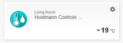
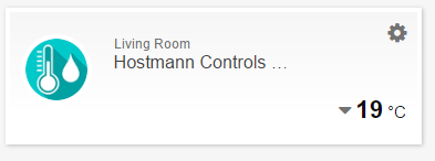
Including it into my ZWave network was straightforward. And it appeared in the SmartHome UI:


And here are some of the views from the Expert UI:

Interview Tab showing supported command classes
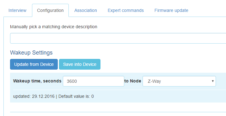
Configuration Tab
Association Tab


but I wasn't sure what to expect after that. According to the ZWave.me forum it is not yet supported by ZWay, but a couple of people had managed to catch a single click event which was all I needed. So I started fiddling with it and seeing what messages appeared.


What happens for a single button press?

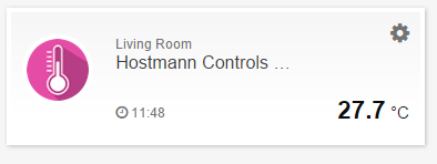
Pressing the button once resulted in a notification appearing in the SmartHome UI:


Looking into the log file, the first message picked up after this button press was:

[2016-12-30 14:48:07.676] [D] [zway] RECEIVED: ( 01 08 00 04 00 28 02 98 40 01 )

followed by a series of SENDS and ACKS

and then what looked like the information I needed:

[2016-12-30 14:48:08.319] [D] [zway] SETDATA devices.40.instances.0.commandClasses.91.data.sequence = **********
[2016-12-30 14:48:08.319] [D] [zway] SETDATA devices.1.instances.0.commandClasses.91.data.srcNodeId = 40 (0x00000028)
[2016-12-30 14:48:08.320] [D] [zway] SETDATA devices.1.instances.0.commandClasses.91.data.srcInstanceId = 0 (0x00000000)
[2016-12-30 14:48:08.320] [D] [zway] SETDATA devices.1.instances.0.commandClasses.91.data.keyAttribute = 0 (0x00000000)
[2016-12-30 14:48:08.320] [D] [zway] SETDATA devices.1.instances.0.commandClasses.91.data.currentScene = 1 (0x00000001)
[2016-12-30 14:48:08.320] [D] [zway] SETDATA devices.40.instances.0.commandClasses.91.data.keyAttribute = 0 (0x00000000)
[2016-12-30 14:48:08.321] [D] [zway] SETDATA devices.40.instances.0.commandClasses.91.data.currentScene = 1 (0x00000001)
[2016-12-30 14:48:08.378] [I] [core] Notification: device-info (device-OnOff): {"dev":"Fibar Group (40.0.0.1) Button","l":"on"}

From the ZWave.me documentation command class 91 is a 'central scene command':


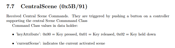
I did a little experimenting here and found that the following keyAttribute values resulted from Fibaro button presses:


press 1 time: 0x00
press 2 times: 0x03
press 3 times: 0x04
press 4 times: 0x05
press 5 times: 0x06
hold down: 0x02 followed by 0x01 once released

But really I was only interested in 'has it been pressed' rather than how many times or for how long. Still, it is good to know that even though the button is not officially supported it is possible to use all of its features. For my purposes I just needed to bind to changes in the keyAttribute.

Binding to the keyAttribute value

Here is my code:

        // find the hot water pump switch
         hotWaterSwitch = getDeviceByManufacturer(FIBARO_ID, FIBARO_BUTTON_ID, FIBARO_BUTTON_TYPE);
         console.log ("MYTESTMOD: hot water switch is " + hotWaterSwitch);
         if (hotWaterSwitch != -1) { 
            zway.devices[hotWaterSwitch].instances[0].commandClasses[91].data.keyAttribute.bind(
                                                      function() 
                                                      {
                                                        self.rooms[1].setPumpStatus(true);
                                                      });
         }
         else {
            controller.addNotification("error", "No Hot Water Switch Present", "module", "MyTestMod");
         }
         self.hotWaterSwitch = hotWaterSwitch;

And here is my button:


currently residing on top of my radio, close to the sink. Working great so far!

Thursday, December 15, 2016

Remote Control of the hot water pump

Next step was to replace the timer switch for the hot water pump with a Z-Wave switch. I already had a Hostmann / Secure ASR-ZW boiler receiver unit that I had bought with the room thermostat and decided to use this. I had some doubts about the switch suitability because of something I had read on the HeatGenius website.


However according to the pump specification the maximum operating current is 0.47A at startup and the switch has a current limit of 3A so I didn't see a problem.

I left the installation to my husband! He added it alongside the existing timer such that we would be able to revert to the old method should the Z-Wave solution fail in some way.

The Hardware


New Z-Wave Switch alongside existing timer control


And the hot water pump 

Once installed, he checked that the on/off buttons were operating the pump and then left the remote part to me.

The ZWay SmartHome User Interface


The switch was easily included in the Z-Wave network and showed up in the ZWay web based UI (SmartHome) as two virtual devices as follows.

Which correspond to the two command classes ThermostatMode (64) and SwitchBinary (37)

Switching either to the on position resulted in the on light illuminating at the switch and the pump operating. And switching either to the off position resulted in the off light illuminating and the pump turning off.

All these events appeared in the event log of the SmartHome UI.

However, pressing ON or OFF at the switch did not result in the status being fed back to zway and nothing appeared in the event log. In order to report the actual status of the switch it is necessary to poll by forcing a SwitchBinary Get to be sent to the switch. This was not a big issue to implement in my ZWay module.

      // poll for the hot water pump status
      // this is necessary because if the pump is activated manually we do not receive a notification
      zway.devices[pumpController].instances[0].commandClasses[37].Get();

See this post for the Vera Controller that reports the same experience.

Adding control to my API


Either of the zway virtual devices created allow the pump to be turned on and off but I opted for the SwitchBinary (37) for my control. This can be activated from the browser with this command:

http://192.168.1.180:8083/ZWaveAPI/Run/zway.devices[37].instances[0].commandClasses[37].Set(true)

which I added to my ZWay module on the rPi:

Room.prototype.setPumpStatus = function (status) {
  console.log("setPumpStatus status is " + status + " (" + typeof(status) + ")");
  // set the actual status and wait for the response before updating our data
  // structures and starting the timer if necessary
  zway.devices[37].instances[0].commandClasses[37].Set(status);
}

registered GET and POST elements with my API:

    zAutomationAPI.router.get("/hillview/pumpstatus/:roomID",zAutomationAPI.ROLE.USER,getPumpStatus,[parseInt]);
    zAutomationAPI.router.post("/hillview/pumpstatus/:roomID",zAutomationAPI.ROLE.USER,setPumpStatus,[parseInt]);

and tested using a Python script.

By default, if the ASR-ZW is turned on it remains on for 45 minutes unless instructed otherwise. It is good to know that it will not remain on indefinitely. However, 45 minutes is way longer than required so I have set the rPi to automatically turn the switch off after 5 minutes of operation. I have made this timer configurable and also report how long the pump is running for. This required two further additions to the API:

pumpDuration GET & POST
pumpTime GET

Adding control via my Android App


I added a button to the Android App which operates the same as the on/off buttons on the device itself.


This has been operating the pump successfully for over a week now. The pump is only running when actually needed and I no longer have to rely on timed intervals to have hot water in my kitchen and utility room. Really pleased with the result!

However a hardware button in the kitchen would be much more convenient. On to the next step.

Sunday, July 24, 2016

Phase 2: expanding the network - adding more radiators

Satisfied with the operation of my zwave network in the living room I purchased two more radiator valves in order to extend the network into neighbouring rooms.

Unfortunately, the signal from the raspberry pi was not strong enough to reach the office TRV from the living room. I moved the rPi into the side room and still it could not connect and it stopped reaching the remotest of the TRVs in the living room (approx 11m away).

The Razberry daughter card did not seem to be up to the job of getting the signal to extend beyond a single room in my house. Perhaps if the walls weren't so solid I may have had more luck, but I certainly was not the only one with issues as reviews were not always favourable regarding reported range versus the actual range.

The best solution would probably have been to add an aerial, which is what several people had successfully tried but I was not confident that my soldering skills were up to the job. Instead I thought I would try adding signal boosters in the form of zwave sockets. This is the approach that HeatGenius take.

Smart plugs extend the range of Heat Genius components in large homes
I purchased this smart socket from Aeon,


It extended the range slightly, but still not satisfactorily. I had similar results from a second socket from TKB:


I spent a lot of time moving my raspberry pi and these sockets about the house trying to figure out whether I would ever be able to get a reliable network. This involved much including/excluding of the sockets and extension cables (in order to position the sockets in line of sight).

Moving the sockets further and further from the raspberry pi would eventually result in the 'update' command failing in the Expert UI routing table. However, at this point the switches were still reachable from the UI and could be turned on/off. It looked like they were still able to operate as switches, but were unable to route.

There were messages in the server log indicating that neighbour reports were failing but I could not see why and the reports were not at a low enough level to glean any useful information.

I was getting ready to throw in the towel at this point, which was a shame as I had already invested quite a bit of time in designing the software and I liked what the ZWay server had to offer.

But based on this amazon review of a dedicated zwave repeater from Aeon:


I decided to have one final stab at the problem and purchased one for myself.


This made a huge difference and I was able to get two more rooms added to my network.

UPDATE June 2017: I ended up purchasing three of these range extenders and re-positioned my raspberry pi upstairs pretty central in the house. Also, I now have a mains powered switch for the boiler control and another for the hot water pump. The network has been working reliably for over six months and reaches TRVs at both ends of my house. End to end my house is about 22 metres and the routing table shows that multiple hops are required for some nodes:


Saturday, June 25, 2016

Phase 1: controlling the heating in the living room - a review

Raspberry Pi connected to ZWave and WiFi networks
One of the most frustrating aspects of our original system was the amount of energy we wasted heating a large living room (approx 27' by 27') which is rarely occupied. The usual pattern is for one or more of us to enter the room in the evening to watch some television - maximum time spent is probably around two hours. The three TRVs were manually turned to the max setting.

Invariably we forgot to turn them off. This meant when the central heating came on the next morning we wasted about 2-3 hours re-heating a room we didn't go in. And in the depths of Winter when we had the heating on all day this problem only got worse.

So, phase 1 was to address this problem.

I already had a raspberry pi, so I just bought the following items to get going with:

3 Danfoss Living Connect TRVs
1 razpberry daughter card
1 Hostmann Controller
2 TRV adapters (required for 2 out of the three radiators)

Here is a layout of the room and where all the components were sited.


At first, I programmed the setup so that the TRVs matched the set point on the Hostmann controller. This made it simpler to turn the heating up or down in the room as it now only required one action. But it did not entirely address the problem of forgetting to turn the heating off on exit. Zway does provide a built in web page UI from which it was possible to adjust the Hostmann control remotely:


This was an improvement as we could at least turn off the TRVs after we had gone to bed rather than try to remember to do so early in the morning.

This worked very well and ran pretty much like this throughout the winter.

I am certain we saved on our gas bill but it would be difficult to put an exact figure on the savings.
There was a definite drop in gas usage from the previous year, but the winter of 2015/16 was milder than the previous one. However, this was a great first experiment and really highlighted how much better things could be. I looked forward to expanding the network.

Friday, February 05, 2016

Choosing the z-wave TRVs

After initial investigations involving the Raspberry Pi, ZWave daughter card and Hostmann thermostat it was time to think about choosing the radiator valves. The two main competitors are the

Z-Wave Danfoss LC-13 Living Connect Radiator Thermostat


They appear to be equally respected across the home automation forums in terms of reliability, battery life and ease of connection. Aesthetically I prefer the Danfoss valves and it is these that HeatGenius adopted for their system. The only doubts I had were over problems that people reported with the early versions, but these seem to have been fixed with version 2. I decided I would purchase a single Danfoss valve to try out.

But how easy would it be to add the Danfoss valve to an existing system?

According to the manufacturer "The battery-powered thermostat is easily fitted to most radiator types in just a few minutes, " and online videos seemed to back this up. Further investigation revealed that it comes with two types of adapter

RA and M30 x 1.5(K) valve adapters

which is probably fine for the majority of UK homes. However, older houses like mine tend to have a mix of valves of various ages that have been added over time, so it was time to carry out a radiator audit.

The results of my radiator audit

17 radiators in total

3 old school radiators with no TRVs
2 radiators with Honeywell TRVs
6 radiators with Pro Heat TRVs
6 radiators with Giacomini TRVs


Honeywell TRV Giacomini TRV Pro Heat TRV

The Honeywell and Pro Heat have heads that screw on and that are interchangeable. I measured the width of the fitting and it was around 30mm. These are M30 heads.

The Giacomini TRV is very different. It is a push on type that is secured with 4 grub screws. I couldn't find anywhere selling such a valve but have since discovered similar valves branded as Barlo, Tower Boss & Harp. I think that they are quite old.

I was confident that the supplied M30 adapters would work with all but the Giacomini TRVs and ordered a single Danfoss LC-13 to get going with. It was easy to install this in place of both the Pro Heat and the Honeywell TRVs, but as suspected there was no suitable adapter for the Giacomini. Unfortunately the Living Room has two of these (and a Pro Heat) and as this was to be the first of my controllable rooms it was important to find a way of adapting or replacing these valves. I certainly did not want to be draining down the system to install new TRVs at such an early stage in the project.

A word on radiator adapters

Most TRVs sold in the UK today are of the M30 x 1.5mm variety. M30 refers to the 30mm measurement across the thread and 1.5mm is the pitch of the thread. Standardizing this fitting has allowed heads from other manufacturers to be fitted onto already installed bodies. However, many homes are fitted with older, less standard valves whose bodies will not work with M30 heads or whose pin size is incompatible.

This has led to the marketing of numerous valve adapters allowing M30 valve heads to replace older (perhaps malfunctioning) heads without the need to replace the whole body (with its associated installation costs).

It was my understanding that if a suitable adapter could be found then I could use this in addition to the M30 to Danfoss adapter supplied. So, the search was on:

Vesternet (from whom I purchased my Danfoss valve) sell a few adapters:

M28 - Comap
M28 - Herz
M28  - MMA or S&B

but none are compatible with my Giacominis.

The only place in the UK that I could find a suitable candidate was Heating Controls Online:

Click here to go to actual page
The picture is not at all clear so I contacted Heating Controls Online for advice. They were very quick to respond and assured me that this was what I was looking for.

I had also seen what looked like the same thing for sale on ebay and amazon (both from Germany). In Germany, the TRV brand is Heimeir but it looks identical to the Giacomini. And here is a picture of the adapter showing the part number as 9700-33.

HEIMEIER-Adapter-fur-Giacomini-Ventile-9700-33-700


With postage, they are no cheaper than those from the UK. At around £15 each, it is an expensive solution but I took a chance and ordered two from heatingcontrolsonline. On arrival I noted the same part number as those sold from Germany which gives an extra purchasing option in the future.

Fitting the Living Room TRVs

I removed the Giacomini heads from the living room and fitted the adapters. This was a bit fiddly as they are not screw on and require a tiny allen key. Once fitted I screwed the M30 adapter on top and fitted the Danfoss Living Connect. The fit is secure, but I am not sure the pin gets pushed completely to the bottom so it is possible they may not close completely. It is a good enough solution though.

By this stage I had had some time to experiment with controlling the single Danfoss LC via the ZWay software on the Raspberry Pi and was satisfied with the results. I ordered two more Danfoss TRVs and got ready to take control of the Living Room.

For anyone having issues finding suitable adapters, this handy chart lists out many TRVs around in the UK and HeatGenius have a useful online compatibility checker.


Tuesday, February 02, 2016

Connecting my first ZWave device - the room thermostat

Once the raspberry pi was up and running as a ZWay server it was time to add my first ZWave device, the room thermostat:

Front, showing display and wheel
Rear, showing DIP switches

For a newbie, the instructions that came with it weren't obvious, so I adapted the instructions that someone had published for connecting to a Vera controller.


  1. Enable DIP switch #1 of the SRT321 thermostat (ON)
  2. Spin wheel of SRT321 until it shows "L" on the screen
  3. Goto the SmartHome UI
    <IP address>:8083/smarthome
  4. Navigate to Devices > ZWave from the cog menu on the top right
  5. Click on autodetect
    Start inclusion
  6. Press wheel on SRT321 to include it
    "L" flashes and changes to "LP"
  7. The SmartHome UI should see the device
  8. Spin wheel to "n" and press
    This sends a node information frame
  9. Disable DIP switch #1 - normal mode (OFF)
    Remove battery for 5 seconds and reset
The thermostat was included first time, much more easily than expected and appeared as three devices in the SmartHome UI


Having a genuine device in the network allowed me to explore 
  • the SmartHome UI, 
  • the HTTP traffic between the ZWay server and the SmartHome UI (using fiddler)
  • the Expert UI
  • the zway server log
  • the ZWaveAPI and the ZAutomation/api/v1
Next step was to write a test module and include it in the ZWay server.


Sunday, January 03, 2016

Getting Started - Raspberry Pi & ZWave

Before buying any kit I took a brief look at the complete solutions on offer:

Heat Genius
Nest
Hive
Tado

I really liked the look of the Heat Genius solution and thanks to a demo available through a web browser or as a phone app I got to have a good play around. It uses ZWave as its communication protocol for which there are plenty of blogs around detailing diy-er's experiences.

J Heyman's Blog
Steve Prater's Blog
Darren Miller's Blog

The Heat Genius system consists of the following components (some of which are used by the bloggers above).

Controller (Heat Genius)
Master Thermostat (Horstmann HRT4-ZW  / Secure SRT323)
Boiler control (Horstmann ASR-ZW / Secure SSR303)
TRVs (Danfoss Living Connect)
Philio Multisensor PIR/Temp/Light

It has been around since at least 2014 and user experiences have been positive. Although the thermostat and phone app aren't as slick as those from Nest, Hive & Tado I think the functionality is better. I decided to model my own system roughly on that of Heat Genius and opted for a Raspberry Pi as a controller (mainly as I had one already). And by choosing some of the same devices I would always have the option to switch to the Heat Genius system if things didn't work out with my own design.

But before buying anything, I installed the zwave.me software on my existing Raspberry Pi image just to get a feel for what it involved. These were the instructions from the ZWave.me site:

First installation when Raspberry is already up und running
To download Z-Way for your RaZberry, login to your Rapsberry Pi box execute the following command:
wget -q -O - razberry.z-wave.me/install | sudo bash

This was a good sanity check to see if everything loaded okay before investing in the hardware. And in fact I managed to glean a lot more information just by poking around in the code than reading the documentation.

It had been a good few years since I had worked on a unix based system - the directory structure and commands largely a distant memory. Stepping carefully through the install process and seeing what processes were generated and where files ended up in the directory structure was an important step for me.


The most important directory and file changes made by the install script were as follows:

  • /opt/z-way-server - where the zway software is installed and where any customization will occur
  • /etc/z-way -  a depository for VERSION and box_type details
  • /etc/init.d/z-way-server - a zway server startup script
  • /var/log/z-way-server.log - anything that the zway system logs gets put here
  • /etc/logrotate/z-way-server - z-way-server.log is added to the rotating logs
And the new processes created were:

  • z-way_server - the all important ZWay server
  • zbw_connect - for connecting to z-wave.me
  • mongoose - provides a web interface (for upgrading the firmware?). It is not the same web interface available on port 8083
Next step, I bought the razberry daughter card and a Thermostat to play around with.


Friday, January 01, 2016

In the Beginning - The Central Heating


Our central heating / hot water is a standard system consisting of a boiler, hot water cylinder, thermostat (in the hall), programmer, 17 radiators (mostly fitted with TRVs), valves, pump and a tank in the loft. There is just one feed & return loop.

The programmer is used for both the heating and the hot water. It is set on a 24 hour basis.

Honeywell Thermostat Honeywell ST699 Programmer Potterton Profile 60E
Central Heating Pump Typical TRV Motorized Valves

In the Winter, the central heating is set to come on for a few hours in the morning and again in the evening with occasional boosts during really cold spells. When the central heating is activated, water is pumped around the whole house via a Grundfos pump.

Radiators are individually controlled by TRVs and are often left heating empty rooms - the biggest culprits are the living room, the utility room, my husband's office and the kids' rooms.


Hot Water Pump Hot Water Timer

In addition, the hot water has a separate timer which is used to operate a pump responsible for delivering water to the whole house. When we moved in, I assumed that this was just to speed up the delivery of the hot water to more remote parts of the house. However, the reality is, that without this additional pump being activated no hot water ever gets delivered downstairs however long you wait for gravity to do its thing. Much of the pipework is concealed, so it is difficult to see what is going on. Plumbers have been puzzled by this too.

If the boiler is off and the pump is left running, a cylinder of hot water cools quite quickly despite no water being drawn off. This would suggest the circulation of the water is a huge waste of energy.

There are three main things I would like to achieve:

1. Create separately controlled heating zones (possibly down to individual rooms)
2. Operate the hot water pump from downstairs only when required
3. Control everything from a phone or tablet