Pages

Friday, May 12, 2017

Let there be light


After getting the Amazon Echo to activate my central heating system one nice feature that fell out of the development was the ability to voice activate a couple of power sockets I was using as ZWave repeaters. This opened up a really convenient way of turning lamps on and off and my husband urged me to buy some more sockets.


The trouble is, ZWave kit is expensive and at about £30 per socket I wasn't sure the expense would be worth it. On the plus side, more ZWave sockets means more repeaters which will add to the robustness of the ZWave network. But before going down that route I looked at some other options.

The great thing about the ZWay system is that it is not dedicated to ZWave. As long as you can create an HTTP connection to something it can be integrated into ZWay and appear as a device. And that device can either be operated from their SmartHome UI, added to my own Android app or operated via my newly written Amazon Alexa skill.

Alternative Alexa enabled lighting solutions

There are numerous 'smart lights' which will already work with Alexa and could probably be integrated into ZWay. This article has a good list. 

The most promising candidates looked like
  • TP Link
  • Philips Hue
But still not that cheap, so ZWave wasn't looking that bad. Could I go cheaper?

The DIY lighting solution


Then I came across these RF power sockets
There are many manufacturers of similar products (some cheaper alternatives) but what I liked about this set was that you get two remotes and other people had already successfully sniffed (and replicated) the RF codes.

What I needed to do was to replicate the RF remote with a WiFi enabled microcontroller which could connect to my ZWay hub and out to the internet:

Replicating the RF remote


For the microcontroller, I started with an Arduino as I already had one going spare.

There are two alternatives to transmitting the RF signal. The more brutal approach is to take the remote apart and hook up the switches directly to the Arduino. I expected this would be my solution and that is why the 2 remote system appealed - if I wrecked it I would still have a usable set of sockets.

The more subtle approach is to use the Arduino to drive a separate RF transmitter module and replicate the codes from the original remote. I already had a cheap 433MHz receiver / transmitter pair which I had bought on ebay. (I would need the receiver to 'sniff' the codes.)


Copying the codes would have been difficult to achieve from scratch but thanks to the excellent RCSwitch library and Pat's well written blog post I had the Arduino connected up and the codes pouring out in no time:

Decimal: 5313843 (24Bit) Binary: 010100010001010100110011
PulseLength: 182 microseconds Protocol: 1


Decimal: 5313852 (24Bit) Binary: 010100010001010100111100
PulseLength: 182 microseconds Protocol: 1

These codes are the on/off for just one socket. I added them to the RCSwitch sample transmit sketch, set the pulse length to 182 and hooked up the transmit module to my Arduino. Next minute, the socket was turning on and off as if by magic.

Getting internet ready


As the Arduino does not have any wifi capabilities built-in I needed some way of adding this functionality. The ESP8266 board is the way most people seem to go, but is apparently tricky to get working. This ESP8266 based board was used in the blog previously mentioned but I was not sure it was available in the UK and decided to opt for the Adafruit version instead. It is a little pricey, but I was wanting to test it out as I have other projects in mind that require the same type of board.

I also bought this console cable in order to connect the laptop to the Huzzah board (and power it). The board comes pre-loaded with Lua, but rather than learn something new I decided to stick with the Arduino IDE. I followed the instructions on the Adafruit website (Using Arduino IDE) and had the standard blink sketch up and running in minutes.

Next I connected up the RF transmitter module:


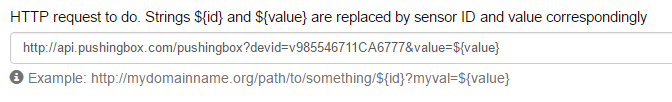
and combined the sample RCSwitch transmit code with the sample ESP8266WebServer code to receive HTTP requests of the form:

http://<local ip address>:8080/socket?id=<n>&state=on and
http://<local ip address>:8080/socket?id=<n>&state=off

(where <n> is a socket id from 1 to 5)

and to send out the appropriate RF codes previously captured.

First hack of code:

#include <ESP8266WiFi.h>
#include <WiFiClient.h>
#include <ESP8266WebServer.h>
#include <ESP8266mDNS.h>
#include <RCSwitch.h>

const char* ssid = ".......";
const char* password = "..........";

// RF stuff
RCSwitch mySwitch = RCSwitch();

char * socketOn[5];
char * socketOff[5];

int transmitPin = 12;
int pulseLength = 182;
int repeat = 3;

ESP8266WebServer server(80);

const int led = 13;

void handleRoot() {
  digitalWrite(led, 1);
  server.send(200, "text/plain", "hello from esp8266!");
  digitalWrite(led, 0);
}

void handleSocket() {
  byte socketID=server.arg("id")[0];
  String state=server.arg("state");

  char * bitSequence = "";

  Serial.write("handle socket\n");
  Serial.write(socketID);
  Serial.write("\n");

  if (state == "on") {
    switch (socketID) {
      case '1': bitSequence = socketOn[0];
                break;    
      case '2': bitSequence = socketOn[1];
                break;
      case '3': bitSequence = socketOn[2];
                break;
      case '4': bitSequence = socketOn[3];
                break;
      case '5': bitSequence = socketOn[4];
                break;
      default: Serial.write("invalid socket num\n");
      }
  }
  else if (state == "off") {
    switch (socketID) {
      case '1': bitSequence = socketOff[0];
                break;    
      case '2': bitSequence = socketOff[1];
                break;
      case '3': bitSequence = socketOff[2];
                break;
      case '4': bitSequence = socketOff[3];
                break;
      case '5': bitSequence = socketOff[4];
                break;
      default: Serial.write("invalid socket num\n");
      }  
  }
  if (bitSequence != "")
      mySwitch.send(bitSequence);

  if (state == "on"){
    digitalWrite(13, LOW);
    Serial.write("socket on\n");
  }
  else if (state == "off") {
    digitalWrite(13, HIGH);
    Serial.write("socket off\n");
  }
  server.send(200, "text/plain", "Socket is now " + state);
}

void handleNotFound(){
  digitalWrite(led, 1);
  String message = "File Not Found\n\n";
  message += "URI: ";
  message += server.uri();
  message += "\nMethod: ";
  message += (server.method() == HTTP_GET)?"GET":"POST";
  message += "\nArguments: ";
  message += server.args();
  message += "\n";
  for (uint8_t i=0; i<server.args(); i++){
    message += " " + server.argName(i) + ": " + server.arg(i) + "\n";
  }
  server.send(404, "text/plain", message);
  digitalWrite(led, 0);
}

void setup(void){
  pinMode(led, OUTPUT);
  digitalWrite(led, 0);
  Serial.begin(115200);
  WiFi.begin(ssid, password);
  Serial.println("");

  socketOn[0] = "010100010001010100110011";
  socketOff[0] = "010100010001010100111100";
  socketOn[1] = "010100010001010111000011";
  socketOff[1] = "010100010001010111001100";
  socketOn[2] = "010100010001011100000011";
  socketOff[2] = "010100010001011100001100";
  socketOn[3] = "010100010001110100000011";
  socketOff[3] = "010100010001110100001100";
  socketOn[4] = "010100010011010100000011";
  socketOff[4] = "010100010011010100001100";

  // Transmitter is connected to Arduino Pin #12
  mySwitch.enableTransmit(12);

  // Optional set pulse length.
  mySwitch.setPulseLength(182);

  // Optional set protocol (default is 1, will work for most outlets)
  // mySwitch.setProtocol(2);

  // Optional set number of transmission repetitions.
  mySwitch.setRepeatTransmit(15);

  // Wait for connection
  while (WiFi.status() != WL_CONNECTED) {
    delay(500);
    Serial.print(".");
  }
  Serial.println("");
  Serial.print("Connected to ");
  Serial.println(ssid);
  Serial.print("IP address: ");
  Serial.println(WiFi.localIP());

  if (MDNS.begin("esp8266")) {
    Serial.println("MDNS responder started");
  }

  server.on("/", handleRoot);

  server.on("/socket", handleSocket);

  server.on("/inline", [](){
    server.send(200, "text/plain", "this works as well");
  });

  server.onNotFound(handleNotFound);

  server.begin();
  Serial.println("HTTP server started");
}

void loop(void){
  server.handleClient();
}

This was tested from a web browser before finally adding each socket as an HTTP device to the ZWay SmartHome UI:


Once added, these were picked up automatically by my Alexa skill during device discovery:


And could then be voice activated:

Providing Power


This was all well and good, but the Huzzah board was still being powered via my laptop so I purchased this breadboard power supply module and found an old suitable ac/dc adapter to power it.

I connected it as follows:


I am using the 3.3V power option on the breakout board and connecting it to the Huzzah V+ pin (rather than VBat). According to the Adafruit website I think I could (and should) use the 5V option but I was not confident enough with electronics to try that. Besides everything ended up working ok at 3.3V.

As I was still in the development phase it was useful to be able to have the option to connect the console cable to a serial monitor. This works by just connecting GND, TX and RX (as shown above).


Final Thoughts


I think that the solution works pretty well for the price and will be a great addition to my project. The Huzzah board is excellent, but I'm going to give the SweetPeas alternative version a tryout too. I have many other mini projects in mind for these boards.

Sometimes the on/off command is missed at the RF connection. I suspect this is to do with the antenna not being quite up to the job. Hopefully this can be improved quite easily, but I think some re-transmissions would help.

Unlike the ZWave sockets there is no feedback at the protocol level to say whether a socket is on or off. If I am in the room then I can see the status, but if I want to put lamps on timers or operate remotely, then I think the ZWave sockets are a better bet.

Primarily, I will be using these sockets as a means of operating several lamps simultaneously in a single room. This can be done by grouping in the Alexa skill, but is probably better done at the RF level by programming all of the Etekcity sockets to obey the same code (this is an option available via buttons on the sides of the sockets).

Monday, March 27, 2017

Alexa, turn on the water pump - OK

With the major goals achieved for my home automation project I felt it was time to add some bells and whistles. First off, voice activation.


Last November's Black Friday event led to the delivery of an Amazon Echo Dot which has been sitting under utilised in the kitchen. I had seen that the likes of Hive and Tado were offering Skills to control their systems and not wanting to be left behind, I looked into how I could add similar functionality to my own system.

I was thinking along the lines of

  • 'Alexa, boost the kitchen for an hour' 
  • 'Alexa, turn on the hot water pump'
  • 'Alexa, who is calling for heat?'

but after some initial investigation I realised that this would require a custom skill and the building of a voice interaction model. This would be way more effort than the end feature would justify. But all was not lost as Amazon provide a simplified framework for home automation projects, the Smart Home Skill SDK.

Amazon's Smart Home Skill 


This takes care of all the extra work by providing a standardized framework of voice commands which would be adequate for my purposes. Some example utterances would be:
  • Alexa, discover my devices
  • Alexa, set the living room to 20 degrees
  • Alexa, turn on the hot water pump
  • Alexa, set the <device name> to 50%
It looks like there are some 'get' commands too, but only available in the US at present.

I could certainly make use of  'turn on the hot water pump' and decided this would be a good first command to implement.

Getting Started with Smart Home Skills

Amazon provides a step by step guide to creating a Smart Home Skill, starting with a prerequisites list:
Signing up for the developer account and the AWS account were straightforward. The developer account is free and the AWS account has a free tier option for light use (requires a credit card though).

The OAuth part looked less straightforward and I was not sure how this was going to work out. However, I ploughed on through Amazon's step by step guide and discovered that for my purposes I could use Login with Amazon as the OAuth server. This worked fine.

The Amazon guide is very good and provides a dummy lambda function (in python) to get going with. The following steps were enough to get communication from Alexa through to the Lambda function and back.


It is important to take it slowly and follow every step. I missed the relevance of selecting the correct region for the Lambda function (EU Ireland in my case) and ended up with no obvious errors during testing, but with my Lambda function not getting called once I had enabled the skill. I wasted a lot of time getting to the bottom of this mistake.

After ironing out the region issue I was able to successfully ask Alexa to "Discover Devices" and could see the dummy device "Smart Home Virtual Device" appear in the Alexa App. Asking Alexa to "Turn On the Smart Home Virtual Device" resulted in an "OK" from Alexa.

The next steps in the guide are about submitting your skill for certification. These steps are not necessary for personal Alexa skills and can be ignored.

My next step was to replace the dummy lambda function with something that actually communicated with my raspberry pi. This turned out to be remarkably easy.


Adapting the Lambda Function

After completing the step by step guide I had a Lambda function sitting in the AWS cloud which was able to receive messages (directives) from Alexa via my Smart Home Skill. The lambda function was just sample code written in Python and which reported a single dummy device capable of actioning 'Turn On' and 'Turn Off' directives.

The code was a single inline python script with the main entry point 

    def lambda_handler(event, context):

I played around with this code for a while to get a feel for which fields were important and what happened when things weren't set up correctly. All of the directives supported by the Smart Home Skill are listed in The Smart Home Skill API Reference another excellent guide from Amazon.

The Directives I was most interested in were:
  • DiscoverApplianceRequest / Response
  • TurnOnRequest / Response
  • TurnOffRequest / Response
  • SetTargetTemperatureRequest / Confirmation

The DiscoverApplianceRequest directive is received at the lambda_handler function when I ask Alexa to discover devices (either via the Echo or through the app). The sample lambda_handler returns a DiscoverApplianceResponse with a single dummy device.

The most important fields in the device details are as follows:

"applianceId":"device001"
"friendlyName":"Smart Home Virtual Device"
"actions":["turnOn","turnOff"]
The applianceId must be unique and the friendlyName is the name that Alexa will recognise when you communicate via speech.

The actions indicate which directives the device supports. The Smart Home Skill will only route through directives listed in the actions. So, if a device doesn't indicate 'setTargetTemperature' in the actions field no amount of shouting at Alexa to set the temperature will route the message through to the lambda_handler.

Communicating between my Lambda function and my raspberry pi


I altered the sample code to return a friendlyName of 'water pump'. Asking Alexa to 'turn on the water pump' resulted in a TurnOnRequest routing through to the lambda_function and a TurnOnResponse being returned. Now it was time to add the actual action of instructing the raspberry pi / zway to turn on the pump.

I already had a load of python scripts that I had used for testing so just copied a few functions into my lambda handler and hoped for the best.

def set_pumpstatus (cookie,id,payload):

    headers={'accept':'application/json','Content-Type':'application/json','Cookie':'ZWAYSession='+cookie}
    # now set the pump status
    r = requests.post(pumpstatus_url+str(id),data=json.dumps(payload),headers=headers)

    return r

Unfortunately the Python requests library is not included in the AWS lambda environment so I was unable to use the 'edit code inline' feature. This turned out to be a minor inconvenience as I just needed to follow the instructions on Creating a Deployment Package (Python) for AWS and upload a zip file with my code in lambda_function.py and the necessary requests library.

# this handles Control directives from Alexa
# it determines which device to control from the id
def handleControl(context, event):
    payload = ''
    header = ''
    device_id = event['payload']['appliance']['applianceId']
    message_id = event['header']['messageId']
    control_type = event['header']['name']
    headerTemplate = {
                "namespace":"Alexa.ConnectedHome.Control",
                "payloadVersion":"2",
                "messageId": message_id
            }
 
    # is it a pump request
    if device_id == pumpDeviceID:
        if (control_type == 'TurnOnRequest') or (control_type == 'TurnOffRequest'):
            cookie = login.send()  
            if control_type == 'TurnOnRequest':
                pumpstatus.set_pumpstatus(cookie,1,{"data":"true"})
                headerTemplate['name'] = "TurnOnConfirmation"
             
            if event['header']['name'] == 'TurnOffRequest':
                pumpstatus.set_pumpstatus(cookie,1,{"data":"false"})
                headerTemplate['name'] = "TurnOffConfirmation"
            header = headerTemplate
            payload = { }
    return { 'header': header, 'payload': payload }  

Remarkably, this went smoothly and within minutes I could turn on and off the water pump with my voice.

Adding more devices and features


The 'devices' I require Alexa to manage are basically the water pump and the rooms (my heating zones). I left the water pump details hard coded into the lambda function but dynamically create the room list by requesting the information from my ZWay server.

The directives I am using for the rooms are as follows:


  • TurnOn / TurnOff - sets boost mode / returns to previous mode
  • SetTargetTemperature - sets boost mode and sets the boost temperature
  • SetPercentage - sets boost mode and uses the % value for the boost duration 1%=1 hour etc.


The lambda function can be found on github with my other zway python scripts.

And here is a demo of the Alexa app logging in to the Smart Home Skill, discovering devices and communicating with them. The status is refreshed on my Android app to show that the operation has been carried out.


Monday, February 27, 2017

Logging Data from my system

Most home automation systems seem to provide some data logging and graphing feature so I decided to look into adding this to my system.

Heat Genius Chart

British Gas Hive Chart


At this stage I am not sure how useful charts of data collected from my central heating system are going to be, but I was keen to learn some new skills. This is a record of my experimenting so far. I plan to add more posts as it develops.

What to log?


There is all sorts of sensor data coming out of my system but the things I am most interested in are:

  • actual temperatures of rooms v desired temperatures over time
  • how often the system is calling for heat
  • external temperature over time
  • actual boiler on/off status
The first three are easily available within my ZWay module. The 4th, the actual boiler status (ie whether it is running) is not available but I have an idea as to how I might measure it using an arduino - but that is a project for another day.

How to log?

The ZWay system already provides a module called SensorValueLogging and from the UI you can easily setup a log to a file or to an external service:

The choices of what to log are limited to actual sensors in the system so it isn't quite what I want. However, it was going to be a good starting point and the code that does it would be very simple to adapt for my own code. But how does it work?

Logging to a file


I activated the module to log the value of one of my thermostats to a JSONFile. The module binds to the value of the thermostat and logs every value change via this piece of code:

            var storedLog = loadObject("SensorValueLogging_" + vDev.id + "_" + self.id);
            if (!storedLog) {
                storedLog = {
                    deviceId: vDev.id,
                    deviceName: vDev.get("metrics:title"),
                    sensorData: []
                };
            }
            storedLog.sensorData.push({"time": Date.now(), "value": vDev.get("metrics:level")});
            saveObject("SensorValueLogging_" + vDev.id + "_" + self.id, storedLog);

This resulted in a SensorValueLogging json file appearing in the storage directory of my ZWay server:


inside I could see a JSON object containing {timestamp, value} pairs for my thermostat:


sensor data displayed via http://jsonviewer.stack.hu/


I could certainly mimic this operation in my own code but was a little puzzled by how loadObject() and saveObject() resulted in such strange file names. The source code was not easily available so I turned to the zwave forum and this post gave an explanation.


I had a quick look at what MD5 is and was satisfied that all I needed to know was that loadObject() and saveObject() would provide a mechanism for me to store and retrieve collected data locally on my rPi (if that is what I decided to do). Someone on the ZWave forum did this a couple of years ago and also provided some web pages to display the data (via Google Charts).

However, I was more keen to investigate sending the data into the cloud.

Logging to the cloud

A quick google search for cloud data logging services and I was overwhelmed by choice. Obviously most of these are commercial based for huge quantities of server data. Where to begin?

Then I came across this page from The Complex and Sustainable Urban Networks (CSUN) Laboratory at the University of Illinois at Chicago. They have been logging temperature and humidity data from an arduino since 2014. The data is logged to a Google Spreadsheet every 10 minutes (via PushingBox) and is then extracted and displayed with Google Charts. Perfect.

I signed up to PushingBox and reconfigured the SensorValueLogging module to send its readings to PushingBox:


The devid was just that of the demo scenario that is automatically created when you sign up. It was linked to a service that sent an email to me. I adjusted the email to pass on the temperature reading:


As with the JSON file example, SensorValueLogging binds to the value of the Thermostat and logs every change. But for HTTP logging it runs this piece of code:

        if (self.config.logTo === "HTTPGET") {
            http.request({
                method: 'GET',
                url: self.config.url.replace("${id}", vDev.id).replace("${value}", vDev.get('metrics:level'))
            });
        }

This did indeed end up sending me emails every time the temperature changed in my office:


PushingBox to Google Docs

Next step was to push the data to a Google Spreadsheet rather than to an email account.
I used this excellent instructables guide to help me through. The interface has changed a bit since that was written but the steps are all valid. Essentially I needed to make PushingBox mimic what happens when data is submitted via a Google Form to a Google Spreadsheet. So, I started by creating a form and submitting some data.
  • Create a google form here with a single question and a short text answer. 
  • Link the form to a spreadsheet (either existing or a new one) and make the spreadsheet shareable
  • Click on SEND and choose the 'send via link' option.
  • Copy the URL and paste it into a new browser window 
  • Submit a temperature reading via the form
The Instructables guide suggested examining the HTML to find the id of the input box. This does work, but I didn't really understand what I was doing with the information I retrieved. I ran Fiddler to trace the actual message the google forms sends when you press submit.

In my case, it sent the following when I submitted a value of 5.

The URL is the same as the one you see after pressing submit - the one that the Instructables guide asks you to copy.

POST https://docs.google.com/forms/d/e/1FAIpQLSdewH0LtfKOpCDqL_Ydi76dUYxrsZs41YDAHszyuvBstApP4g/formResponse HTTP/1.1

with

entry.463855442=5&fvv=1&draftResponse=%5B%2C%2C%227319728817704999679%22%5D%0D%0A&pageHistory=0&fbzx=7319728817704999679

in the body.

I set up a PushingBox service to attempt to do the same thing:


The full URL can be seen here.


I then added this service to the original demo scenario with the entry data from the body I had captured in Fiddler. $value$ is used to tell PushingBox to substitute the actual value given to it from the ZWay SensorValueLogging module. The rest of the data I had captured in the body I ignored.


And here are the resulting entries in my spreadsheet:


Which I then displayed via google charts thanks to a quick bit of hacking of the CSUN HTML and javascript.


Next step will be to write my own logging object / module and start collecting all of the data I require.